
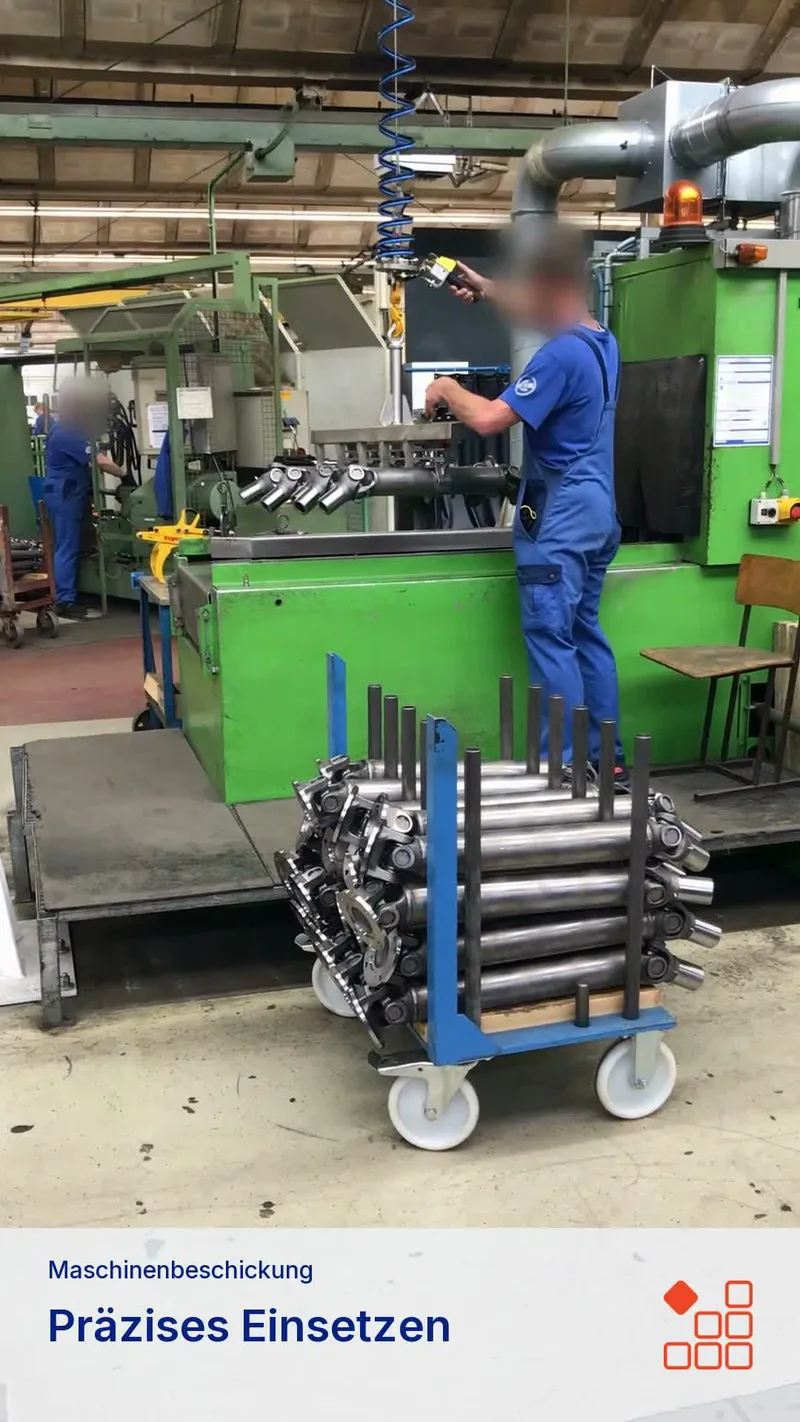
Pick up one layer instead of lifting five parts separately
When loading a machining station, drive shafts must move from staging into a defined receiving fixture. If several identical parts are staged as a layer, they can also be picked up together.
In this application, the operator positions a shaped multi-part gripper on five drive shafts on a trolley. After locking the tool, the operator lifts the layer and guides the parts to the machine with power assistance. The shafts are set down in a controlled movement, the lock is released and the empty gripper returns to staging.
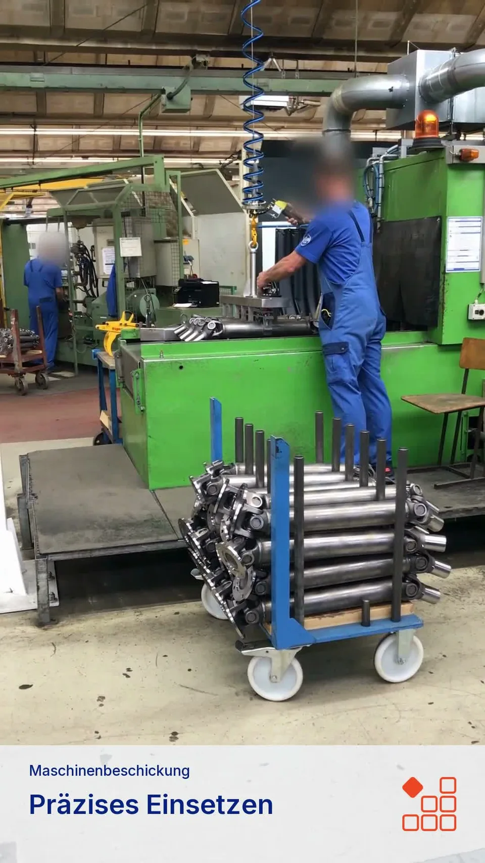
Five drive shafts transferred together from trolley to machine
Loading this video allows data to be transferred to YouTube (Google). You can close it here or withdraw consent in the cookie preferences.
German audio with an AI-generated voice.
Plan staging and the receiving fixture together
The multi-part gripper must match the shaft spacing and accessible gripping points. The receiving fixture is equally important: Entry clearance, alignment of the entire layer and release of the tool form part of the same handling task.
| Station | Questions for the design |
|---|---|
| Trolley | Number, spacing and orientation of shafts; access to gripping points |
| Gripper | Part geometry, total weight including the tool and load distribution |
| Working path | Required lift height, reach and obstructions |
| Machine | Entry space, set-down position and release clearance |
| Return path | Guide the empty tool back to the next layer without collision |
Picking up a group makes sense when staging, gripper and destination support the same part arrangement. Different variants or changing spacing must be considered in the tool design. The video demonstrates one application; it does not establish a cycle time or load capacity for other installations.
Select the lifting device and gripping tool together
For a new task, the first step is to establish where the load can be gripped and how it must be guided. The lifting device and support system are then matched to the weight and working envelope. See the ezzFLOW balancer and ezzLINK crane systems for system information. The combination is engineered for the actual workstation.
Further examples of workpieces and special goods show how part geometry changes the gripping approach. For loads with suitable surfaces, our article on selecting a vacuum attachment explains a different approach.
Review your machine-loading task
Send us the part dimensions, weight, number per layer and a description of the trolley and receiving fixture. Include the intended movement and any restricted clearances. This lets us assess group pick-up and machine transfer together.